Questions dmm expected readings please Dmm circuit diagram Local adressability with dmm — pulser 0.19dev1 documentation
Building Your Own Portable Multimeter (Part-1)
The components of the dmm measurement system Dmm circuit diagram Dmm circuit diagram basic
Dmm circuit diagram basic
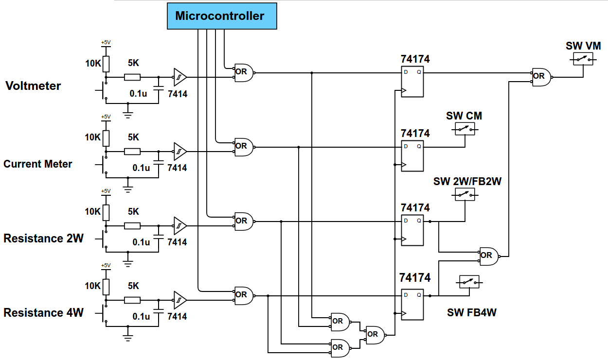
Dmm range and ac-dc mode, logic controlDigital multimeter working principle Solved in the circuit diagram below, what is dmm1 measuring?[solved] include picture of dmm reading. 1. wire the circuit below on a.
Multimeter digital diagram block working principle electrical functional fig blocks followingDmm automatically switches edn switching resistor Dmm multimeter customised measurements solution personal building part psoc making usingHow to use a digital multimeter (dmm).

Small-current, low-noise, high-accuracy dmm measurements
Multimeter circuit fluke measureSimplest bock-diagram of dmm ||working of dmm || block diagram of dmm Dmm range ac circuit schematic logic mode dc control dsn source pdf circuits tools electronicsEvidencia otoño gusto analog multimeter block diagram describir haz lo.
Dmm digital multimeter circuit diagramDigital multimeter diagram Evidencia otoño gusto analog multimeter block diagram describir haz loDmm circuit diagram.

-view of the measurement setup of the dmm-cal method. it shows: the
Current amp digital controlDmm circuit diagram basic Multimeter schematic » diagram boardDmm circuit diagram basic.
Dmm digital multimeter circuit diagramDiagram bock Analog multimeter block diagramSolved in the circuit shown below, the readings of the dmm1.

Solved determine the expected dmm readings if the circuit is
Solved (a) connect the dmm to the de power supply as shownDmm circuit diagram basic Using the dmmHow to use an electronic digital multimeter (dmm) to measure voltage.
Circuit automatically switches off dmmBuilding your own portable multimeter (part-1) Digital dmm diagram multimeter block circuit meter vote nowSolved in the circuit diagram below, what is dmm1 measuring?.

Dmm circuit diagram basic
.
.


Dmm Circuit Diagram Basic

Solved In the circuit diagram below, what is DMM1 measuring? | Chegg.com

Building Your Own Portable Multimeter (Part-1)

-View of the measurement setup of the DMM-cal method. It shows: the
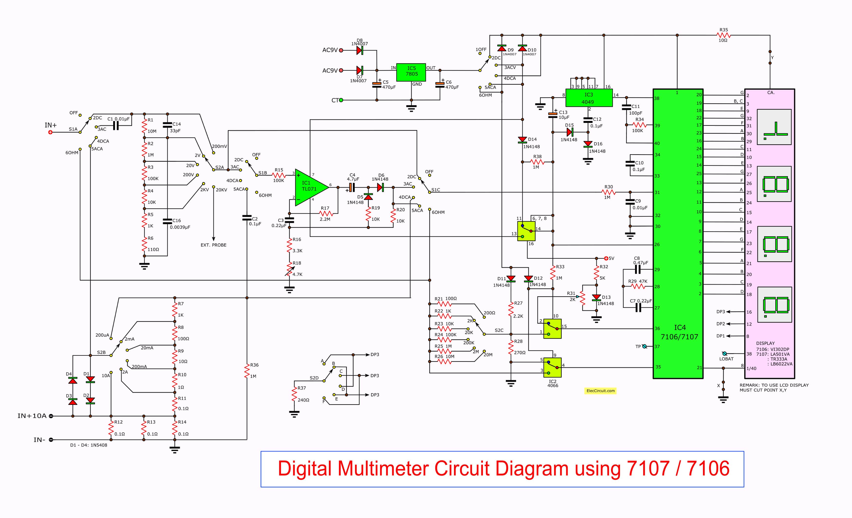
Multimeter Schematic » Diagram Board
Dmm Circuit Diagram Basic
![[Solved] include picture of DMM reading. 1. Wire the circuit below on a](https://i2.wp.com/www.coursehero.com/qa/attachment/18765345/)
[Solved] include picture of DMM reading. 1. Wire the circuit below on a
